If you are an automotive technician, vehicle technician, or a motor mechanic, you may find this cheap yet powerful car battery charger circuit extremely handy, as it can be used for charging all types of car and motorcycle battery overnight with minimum effort.
This charger is specially suited for garages since it has a rugged and a maintenance free design, which allows the mechanic to use it without too many precautions. The only precaution that needs to be taken is the voltage selection between 6 V and 12 V, depending on the battery.
Another advantage of this solid state car battery charger is that the car mechanic can leave the battery unattended after connecting it with the charger, since the charger itself takes care of everything, right from auto full charge cut off to a current a controlled charging.
Main Features
- Inexpensive design, built using discrete ordinary parts.
- Adjustable charging voltage
- Adjustable charging current.
- Fully transistorized Solid State design.
- Suitable for all car and motorcycle batteries.
- Automatic cut off
- Charging level and status indicator
Full Charged Battery Improves Cold Cranking Amps
This circuit can also be used by all motorists so that they can be relaxed, especially on cold mornings. The unit will automatically charge the car's accumulator overnight so that during frozen mornings the car engine starts readily and at the first cranking.
While implementing an overnight battery charging unit, it becomes crucial to ensure that the battery does not get overcharged at any circumstances.
To make sure overcharging can never take place, the output voltage from the charger ought to be limited to the correct safe limit.
For 12 volt batteries the optimal safe charging voltage is approximately 14.1 V and for 6 V batteries it is around 7 V.
The full charge voltage threshold for 12 V car battery is adjusted using preset P2, and for 6 V motorcycle battery it is set by preset P1.
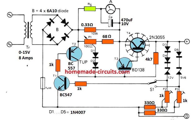
Circuit Diagram
How the Auto Cut-off at Full Charge Level Works
Overcharging situation is controlled through the following circuit operations.
While the battery charges its voltage level slowly climbs higher, until it reaches its 80 or 90% charge level. This is actually set by the presets P2 or P3 as explained previously.
Now, as the voltage level begins reaching the full charge level, the current begins dropping until it reaches almost the 0 amp mark. This is detected by the current sensor stage built around transistor T1/T2, or BC547/BC557, which instantly conduct and cuts off the bias to the base of T3 (BD138).
This in turn dries off the base bias for the power transistor 2N3055, shutting off the charging supply to the battery.
T3, T4 transistors actually behave like a high gain, high power PNP/NPN Darlington pair for effective transfer of current to the connected battery.
How Current Sensor Works
The current sensor stage using T1, T2, and preset P1 can be used for setting any current between 2 and 6 amps for charging the relevant car battery. With 6 amp current a 60 Ah car battery can be charged within 12 hours to 80% level which is almost the full charge level of the battery.
How Charging Status is Monitored
The output charging current or the charging status can be continuously monitored through an ordinary ammeter. This could be any cheap ammeter rated appropriately.
The series resistors Rs is used for suitably calibrating the meter response to full scale deflection initially, and 0V deflection at full charge.
The capacitor Cp ensures that the meter needle does not vibrating due to 100 Hz frequency from the bridge rectifier.
How the Circuit Prevents Desulfation
It must be noted that no filter capacitor is included in this car battery charger circuit, which helps to implement two factors: 1) cost and space saving, 2) Enhance battery life by minimizing the sulfation chances of the plates. The only single smoothing element in the charger is the car battery itself!
How to Set the Presets
As can be seen the presets P2, P3 are associated with a few rectifier diodes and zener diodes. When the 1K preset setting is at the maximum level, it sets the relevant outputs to 14 V and 7 V for 12 V and 6 V battery charging respectively.
The 1 K presets allow the user to fine-tune the full charge level to the preferred precise value. In case the maximum default value fails to reach the recommended levels of 14.1 V and 7 V, the user may add an additional rectifier diode with the existing D3, D4 or D5 diodes, and then tweak the 1K presets until the exact output full charge level is determined.
How to Set the Current Limit
The output current limit can be fixed by appropriately adjusting the P1 preset in the following manner:
Intilally keep the P1 slider towards the 68 ohm resistor.
Connect a 10 amp ammeter across the emitter of 2N3055 and ground.
Now, slowly adjust P1 until the desired maximum current is determined through the meter reading. This will fix the output charging current for the car battery at the required optimal rate.
https://www.homemade-circuits.com/regulated-car-battery-charger-circuit-for-garage-mechanics/
Δεν υπάρχουν σχόλια:
Δημοσίευση σχολίου
Το blog TEO O ΜΑΣΤΟΡΑΣ ουδεμία ευθύνη εκ του νόμου φέρει σχετικά σε άρθρα που αναδημοσιεύονται από διάφορα ιστολόγια. Δημοσιεύονται όλα για την δική σας ενημέρωση.