
Presented here is the circuit that drives twenty LEDs in a random manner. LED flashers and sequencers are used in decorative lights to give pretty colour combinations by glowing LEDs in random or sequential manner. This flasher has a chip that controls the random flashing rate of the LEDs.
Circuit and working
The circuit diagram of the LED flasher using Arduino is shown in Fig. 1. The circuit is built around Arduino Nano board (Board1), twenty coloured LEDs (LED1 to LED20) and a few other components.
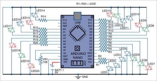
Arduino is programmed in such a way that only one LED glows at a time. A random number is generated by the program that is used to turn on the LED connected to the particular I/O pin of Arduino. On delay time period between any two LEDs or next random LED is controlled using potmeter VR1. Thus, all LEDs flash in a random manner by illuminating one LED at a time. These glow in this pattern continuously until power is switched off or removed.
Arduino Nano
Arduino Nano is a compact and breadboard-friendly board based on ATmega328 microcontroller (MCU). It has similar functionality as Arduino Uno but is available in a different and smaller package.
Dimensions of Arduino Nano are 43mm x 18mm. It has fourteen digitals I/O [of which six are pulse-width modulation (PWM) I/O pins and eight analogue inputs], 16MHz clock speed and 32kB flash memory. It uses a mini USB cable instead of the standard USB one for connecting to the computer. Unlike Arduino Uno, Arduino Nano does not have the DC power jack for external power source.
The software for the flasher is written in Arduino programming language/sketch. Arduino Nano is programmed using Arduino IDE. Select the correct board from Board→Tools menu in Arduino IDE, select COM port and upload the program (Flasher.ino) through the USB port in the computer.
Construction and testing
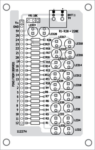
Connect LEDs (LED1 through LED20) to the port pins of Arduino Nano, as per the circuit diagram. You will need a breadboard, veroboard or designed PCB for connecting the resistors and LEDs to Arduino Nano.
A PCB layout of the circuit is shown in Fig. 2 and its components layout in Fig. 3.
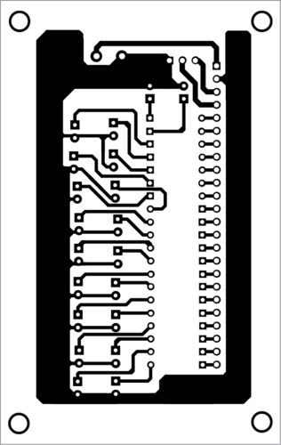
Download PCB and Component Layout PDFs: click here
Download Source Folder
After assembling the circuit on the designed PCB and programming Arduino Nano, connect 9V DC or 9V battery to the circuit. You will notice that all LEDs (LED1 through LED20) start to glow randomly, one-by-one. The LED flashing pattern repeats in this fashion till power supply is switched off.

Many LED strings can be used in place of a single LED using suitable drivers. However, total current of Arduino Nano is limited to 200mA, so it is advisable to use a suitable driver if more than one LED is to be lit at a time. Bi-colour or RGB LEDs can be used instead of single-colour LEDs.
A. Samiuddhin is B.Tech in electrical and electronics engineering. His interests include LED lighting, power electronics, microcontrollers and Arduino programming.
This project was first published on 11 January 2020 and was updated on 14 April 2020.
https://www.electronicsforu.com/electronics-projects/flash-twenty-leds-using-arduino
Δεν υπάρχουν σχόλια:
Δημοσίευση σχολίου
Το blog TEO O ΜΑΣΤΟΡΑΣ ουδεμία ευθύνη εκ του νόμου φέρει σχετικά σε άρθρα που αναδημοσιεύονται από διάφορα ιστολόγια. Δημοσιεύονται όλα για την δική σας ενημέρωση.