
This precision clock uses just two ICs and one junction field-effect transistor (JFET) in conjunction with a commonly available crystal and a handful of other passive components.
The Pierce-type crystal oscillator is formed around BFW10 n-channel JFET using the components as shown in the figure. A commonly available low-priced 4.194304MHz crystal is connected between its gate and drain via capacitor C1. A readymade 100µH radio frequency coil (RFC) forms the load for JFET at crystal frequency and also prevents the RF signal from entering the DC supply.
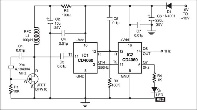
The 4.194304 MHz output from the drain is fed to input pin 11 of the 14-stage binary counter-cum-oscillator CD4060 (IC1). The output from pin 3 of IC1 is equal to the crystal frequency divided by 16,384, i.e. 4.194304 MHz/16,384=256 Hz, which is connected to pin 11 of another IC CD4060 (IC2). The Q8 output from pin 14 of IC2 further divides the input frequency by 256 to give 1Hz pulses (with 50 per cent duty cycle). The LED connected to pin 6 (Q7) of IC2 flickers at the rate of 2 Hz (‘on’ time=0.25 second and ‘off’ time=0.25 second), indicating that the circuit is functioning properly.
https://www.electronicsforu.com/electronics-projects/hardware-diy/precision-clock
Δεν υπάρχουν σχόλια:
Δημοσίευση σχολίου
Το blog TEO O ΜΑΣΤΟΡΑΣ ουδεμία ευθύνη εκ του νόμου φέρει σχετικά σε άρθρα που αναδημοσιεύονται από διάφορα ιστολόγια. Δημοσιεύονται όλα για την δική σας ενημέρωση.