
SPWM waveform stands for sinewave pulse width modulation waveform and this is applied in the discussed SPWM inverter circuit using a few 555 ICs and a single opamp.
In one of my earlier posts we elaborately learned how to build a SPWM generator circuit using an opamp and two triangle wave inputs, in this post we use the same concept to generate the SPWMs and also learn the method of applying it within a IC 555 based inverter circuit.

Using IC 555 for the Inverter
The diagram above shows the entire design of the proposed SPWM inverter circuit using IC 555, where the center IC 555 and the associated BJT/mosfet stages forms a basic square wave inverter circuit.Our aim is to chop these 50Hz square waves into the required SPWM waveform using an opamp based circuit.
Therefore we accordingly configure a simple opamp comparator stage using the IC 741, as shown in the lower section of the diagram.
As already discussed in our past SPWM article, this opamp needs a couple of triangle wave sources across its two inputs in the form of a fast triangle wave on its pin#3 (non-inverting input) and a much slower triangle wave at its pin#2 (inverting input).
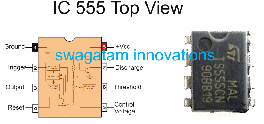
IC 555 Pinouts
Using IC 741 for the SPWM
We achieve the above by using another IC 555 astable circuit which can be witnessed at the extreme left of the diagram, and use it for creating the required fast triangle waves, which is then applied to the pin#3 of the IC 741.For the slow triangle waves we simple extract the same from the center IC 555 which is set at 50% duty cycle and its timing capacitor C is tweaked appropriately for getting a 50Hz frequency on its pin#3.
Deriving the slow triangle waves from the 50Hz/50% source ensures that the chopping of the SPWMs across the buffer BJTs is perfectly synchronized with the mosfet conduct ions, and this in turn ensures that the each of the square waves are perfectly "carved" as per the generated SPWM from the opamp output.
The above description clearly explains how to make a simple SPWM inverter circuit using IC 555 and IC 741, if you have any related queries please feel free to use the below given comment box for prompt replies.
Update:
A deeper investigation reveals that the slow triangle waves must have a frequency of 100Hz and not 50 Hz for creating correctly dimensioned SPWMs, this may be done by using a frequency doubler stage bewtween pin#2 of the IC 741 and the 50Hz from pin#6/2 of the center 555 IC.
https://www.homemade-circuits.com/spwm-inverter-circuit-using-ic-555/
Δεν υπάρχουν σχόλια:
Δημοσίευση σχολίου
Το blog TEO O ΜΑΣΤΟΡΑΣ ουδεμία ευθύνη εκ του νόμου φέρει σχετικά σε άρθρα που αναδημοσιεύονται από διάφορα ιστολόγια. Δημοσιεύονται όλα για την δική σας ενημέρωση.