This article talks about measuring 10 Mbit/s (10Base-T) and 100 Mbit/s (100Base-TX) twisted pair Ethernet signals. Those standards use two wire pairs for the communications and use differential signaling.
Differential signaling is a method for electrically transmitting information using two complementary signals. The technique sends the same electrical signal as a differential pair of signals, each in its own conductor. During a digital pulse, each wire in the pair carries a signal that is the same voltage, but opposite polarity. Differential signaling combined with twisted pair wiring has good noise-canceling capability.
The differential signaling presents soem challenges when measuring the signals with osciloscope. Oscilloscopes typically have single ended probes which has one signal wire and ground. If you are going to measure on a Twisted Pair connection, the chances are that none of the wires are “ground”, so connecting the probe ground to one of the wires *may* cause problem:It will probably do bad things to signal quality, though, thus affecting your readings.
For what regards the “ground” problem, you can use a differential probe or in alternative two probes (A and B) with grounds connected each other and display the difference between them (A-B), once you have connected A and B to the respective wires. Expect to see around ± 2.5V (over twisted pair) on 10BASE-T and three-level signal (1 Volt, 0 Volt, -1 Volt) for 100BASE-TX. NIC (Network Interface Card) that works at 10Base-T mode outputs data at “Manchester Code”, which is pretty easy to interpretate. You can find examples on decoding athttps://goo.gl/photos/3EQojfnYpNPd4fWz7. Trying to decode 100BASE-TX signal is much harder, so you propably need to invest to an expensive instrument with decoding software. This video demonstrates a real example of a Ethernet wire attached to a device with live data.
What are the cheap hacks to seem Ethernet signals on the oscilloscope screen without investing a lot of money? Are some tips:
I have used a passive Ethernet Tap circuit for successfully monitoring 10 Mbit/s and 100 Mbit/s Ethernet traffic. This circuit connects one Ethernet signal to two Ethernet cards that receive it (one the real communicating device and other the monitoring device). This circuit is a widely used hack. It is a hack in a sense that it is not technically up to the specifications an Ethernet device should need, but it is simple and works pretty well in most cases. The simple construction method used in this circuit creates impedance mismatches to the communications line, which are not good for the communications. But because Ethernet is pretty robust technology this “not so good” system works well enough at least with short cable runs on lab.
Then the next step is to replace that monitoring Ethernet card with some interface that connect the signal to oscilloscope. For this task I built this a simple Ethernet line to oscilloscope adapter circuit out of old Ethernet card.
First I picked an old ethernet card (old junk card works):
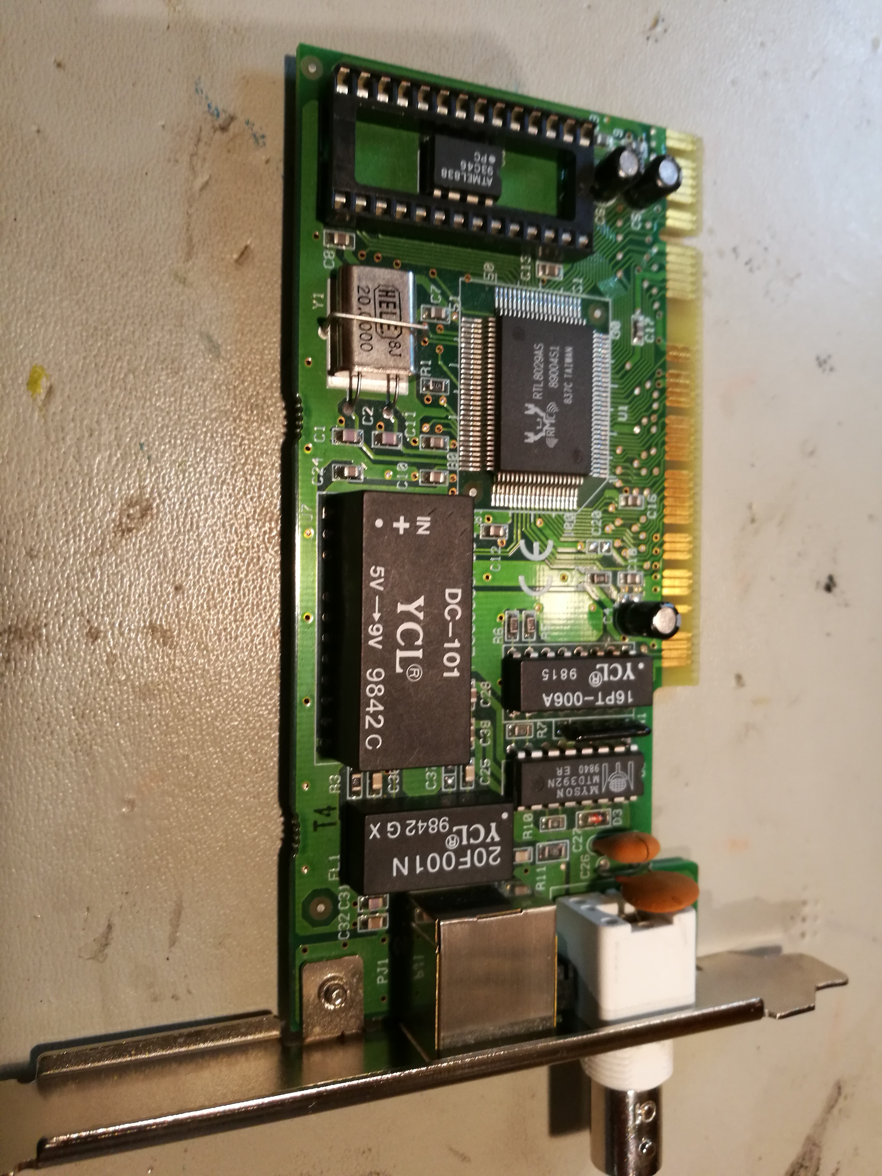
Here is solder side view of the card:
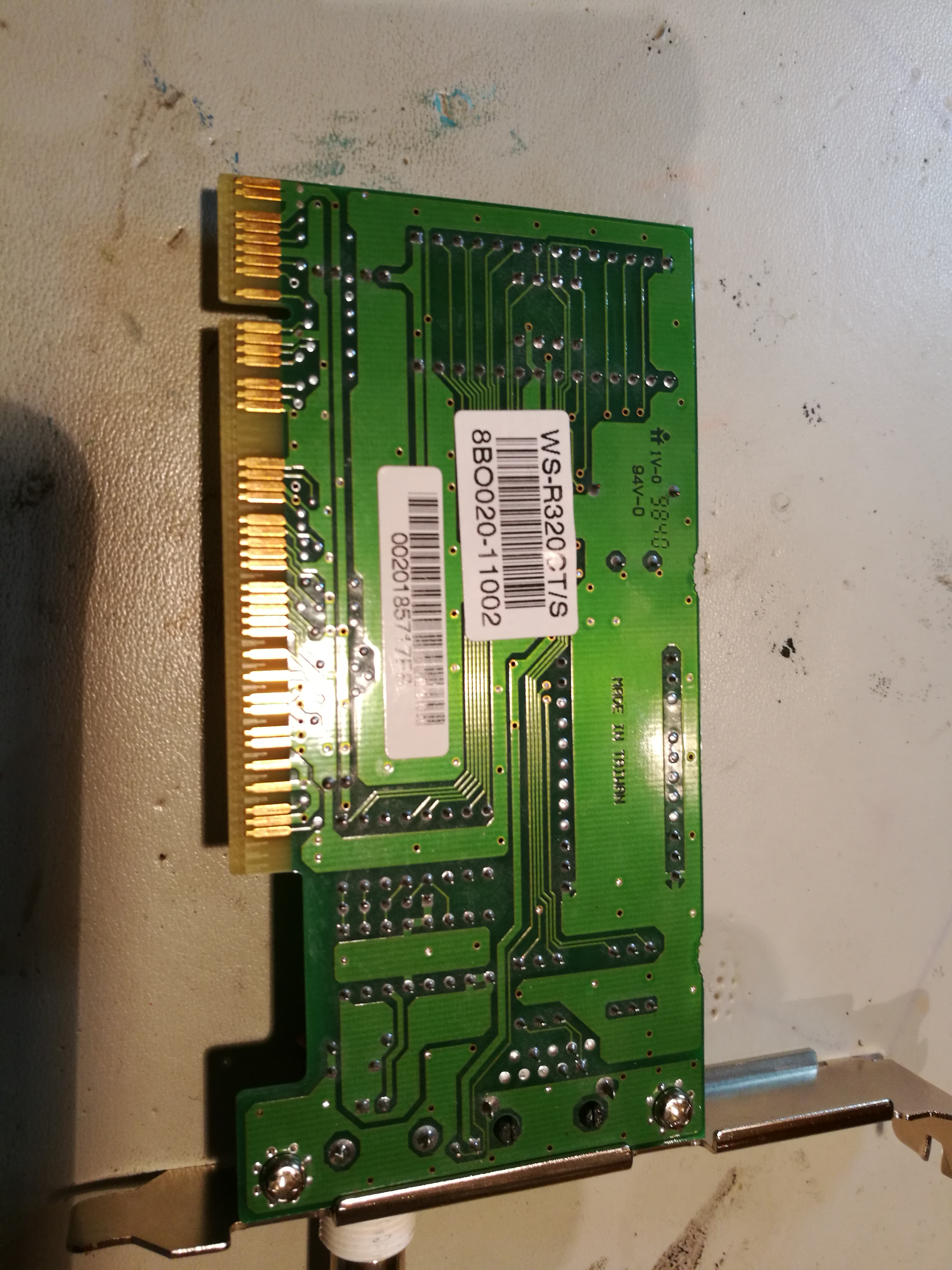
Next find the Ethenret line transformer (bottom right) pins and find out which side is secondary that connect to Ethernet chip instead of RJ-45 connector:
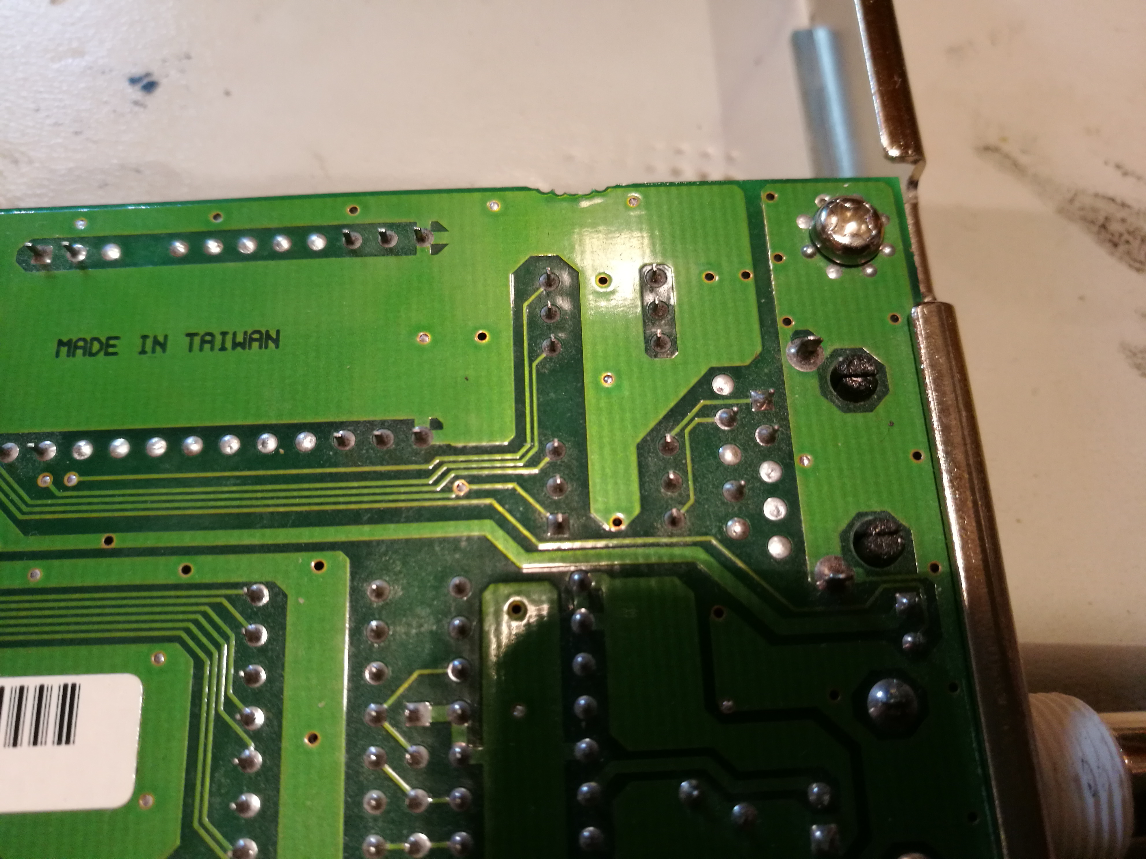
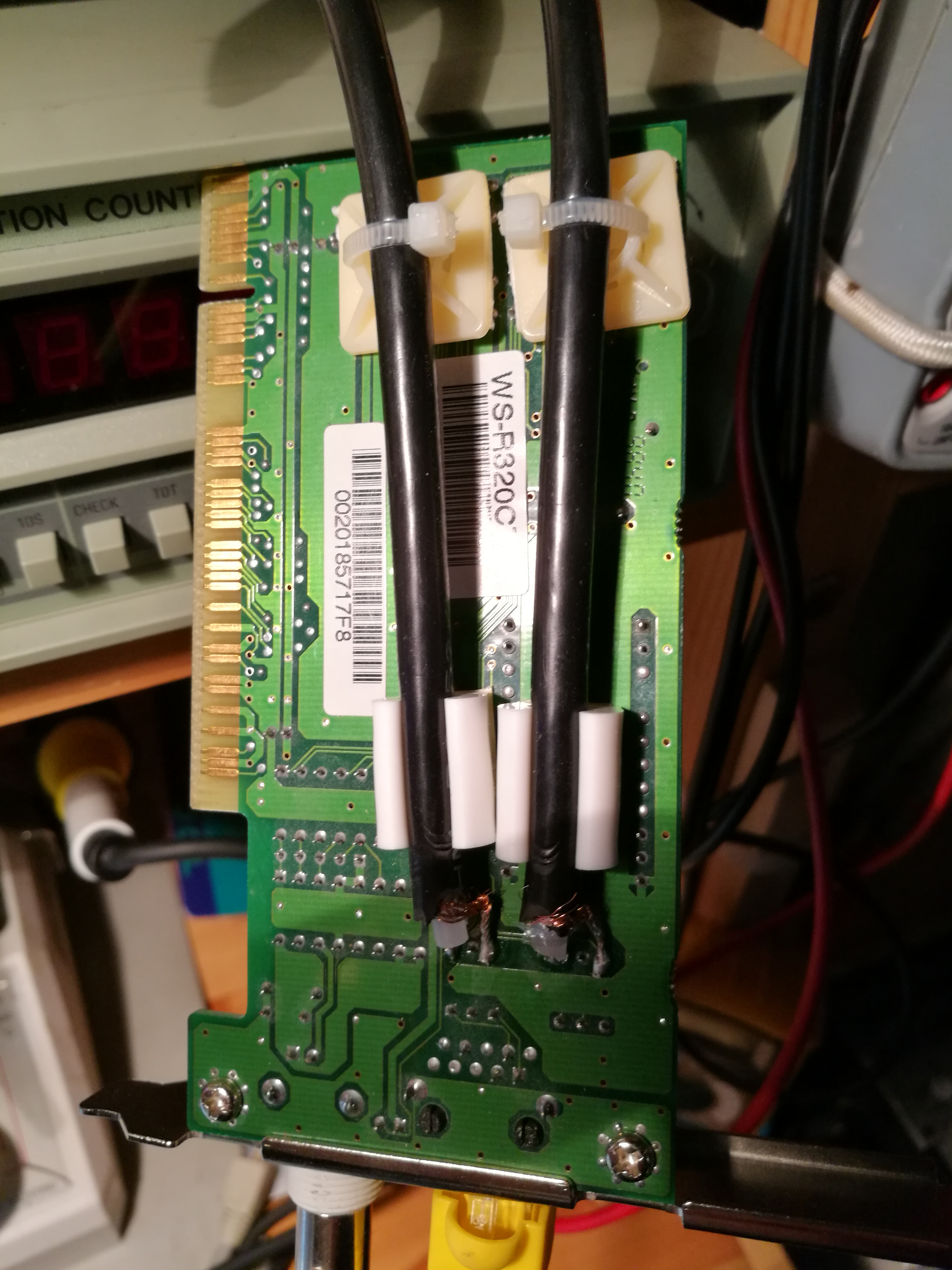
The needed modification is to solder a short coaxial cable (that goes to oscilloscope) to the TX and RX secondary pins:
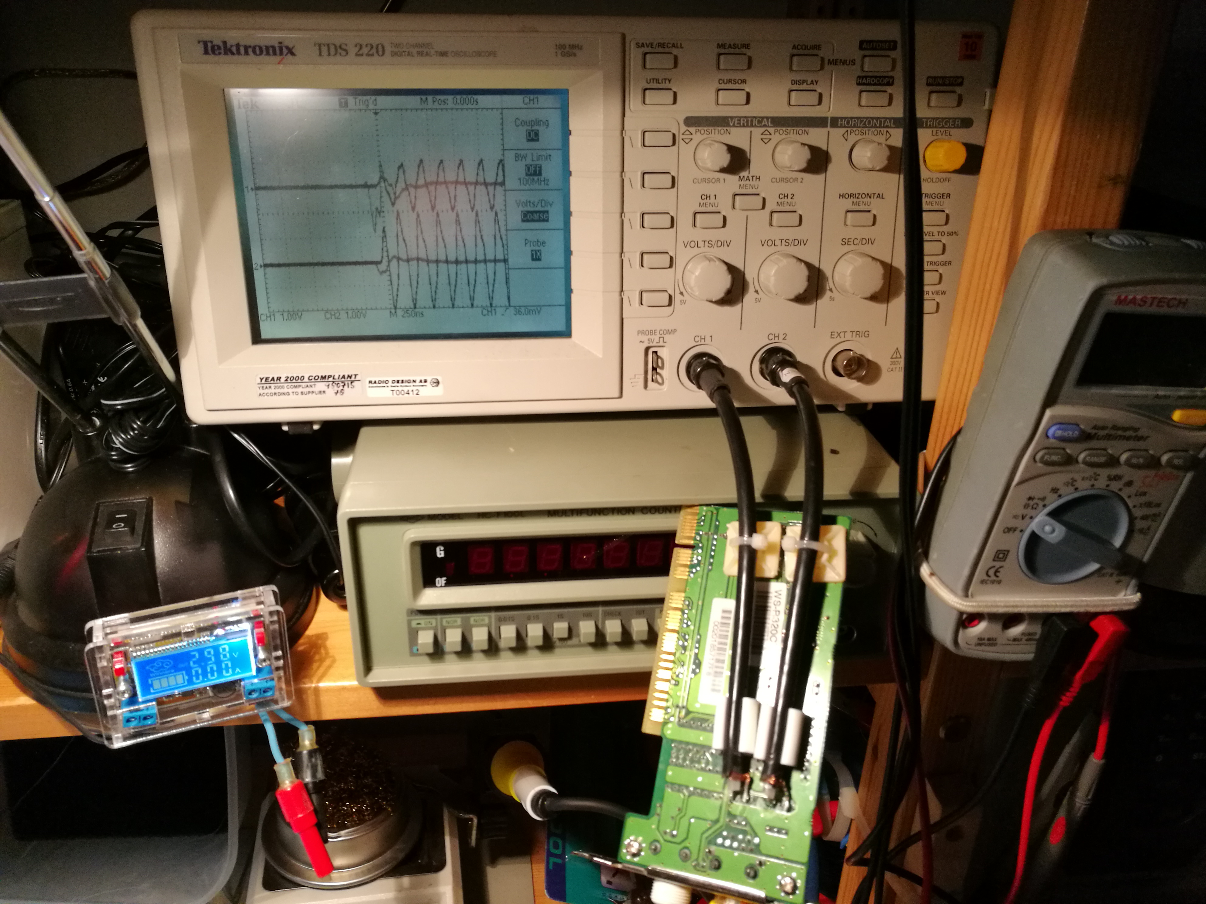
Here are the results on the oscilloscope screen:
http://www.epanorama.net/newepa/2017/07/16/probing-ethernet-cable-with-an-oscilloscope/
Δεν υπάρχουν σχόλια:
Δημοσίευση σχολίου
Το blog TEO O ΜΑΣΤΟΡΑΣ ουδεμία ευθύνη εκ του νόμου φέρει σχετικά σε άρθρα που αναδημοσιεύονται από διάφορα ιστολόγια. Δημοσιεύονται όλα για την δική σας ενημέρωση.