
The post provides an in-depth description of the Flynn motor circuit concept and furnishes the rough replication details for the same.
Parallel Path Concept
In one of my previous posts we got a comprehensive view regarding what's populary known as the parallel path magnetic theory
In this theory a relatively weaker electromagnetic assistance is used for manipulating a massive force obtained from a few enclosed permanent magnets.
The same theory when implemented for acquiring a rotational movement, is able to create to a force which could not be achieved through the conventional motor concepts.
Also called the Flynn motor, the figure below is the basic or the classic representation which shows how the parallel path technology could be implemented for building motors with outstanding efficiency.
Understanding the Flynn Motor
The concept used in Flynn motor is no rocket science rather a very straightforward magnetic theory where the magnetic attraction of permanent magnets is enforced for the generating massive amounts of free energy.
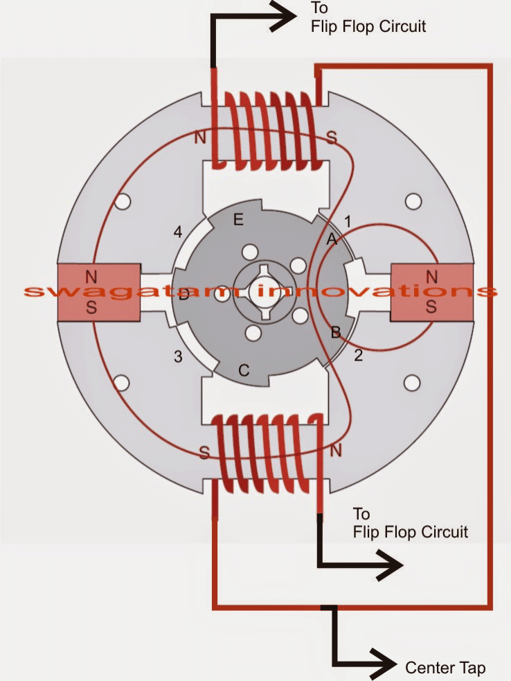
The images below show the basic design of the Fynns motor, which just like an ordinary motor has an outer stator and an inner rotor.
The stator is a stationery structure made out of two ferromagnetic sections specially dimensioned for facilitating the proposed parallel path actions.
Designing the Stator/Rotor
Fundamentally these are two "C" shaped ferromagnetic structures possessing a central block space for accommodating a coil winding, while the ends are chiseled flat for clutching a couple of permanent magnets in between the two "C" structures.
The above structures form the stator.
A circular structure also made up of ferromagnetic material can be seen positioned exactly at the center of the two "C" shaped stator. This forms the rotor of the proposed Flynn motor design.
The above rotor circular structure encloses five projected convex arms at its circumference with a specific cut-out shape which makes a calculated angle with the complimentary concave edges enclosed with the two"C" shaped stator.
The relative angle between the rotor/stator surfaces are configured such that all the surfaces never come face to face at any given instant.
Now let's understand how the wire coil and the permanent magnets interact to generate the proposed extraordinary amount of force over the rotor movement.
Winding Details for the Motor
As long as the winding over the stator is not connected to the specified electrical input, all the four stator's inner concave surfaces exhibit an equal amount of magnetic attraction over the rotor arms keeping the rotor movement uninfluenced.
The above magnetic pull is caused due to the two permanent magnets stationed at the shown locations.
Now as soon as an electrical input is fed across the winding (which must alternate across the two coils at any specified frequency) the rotor experiences the parallel path effect and responds with a high torque rotation with an RPM determined by the frequency applied between the coils by the electrical input .
The rotational influence generated by the parallel effect can be understood by referring to the diagram below.
Now suppose, the initial instantaneous frequency polarity of the coil input pulls the rotor and aligns the A and B arms of the rotor with the 1 and 2 surfaces of the stator, inducing a clockwise movement....
the next instant as soon as the coil polarity is reversed, the above clockwise movement is reinforced as the "parallel path" magnetic pull tries to align the rotor C and D arms with the 3/4 surfaces of the stator....the next polarity change repeats the previous alignment procedure.
The above explained continuous magnetic influence (supported by the outstanding parallel path technology) forces the rotor to undergo a strong rotational motion featured with efficiency exceeding the 100% mark.
The referred exceptional torque is generated due to the parallel path effect through which a relatively weaker electrical input causes the magnetic fields of the enclosed permanent magnets to concentrate on either sides alternately making sure the opposite side is subjected with a zero force simultaneously.
The speed of above flipping action is determined by the frequency of the electrical input across the two winding.
Flynn Motor Schematic
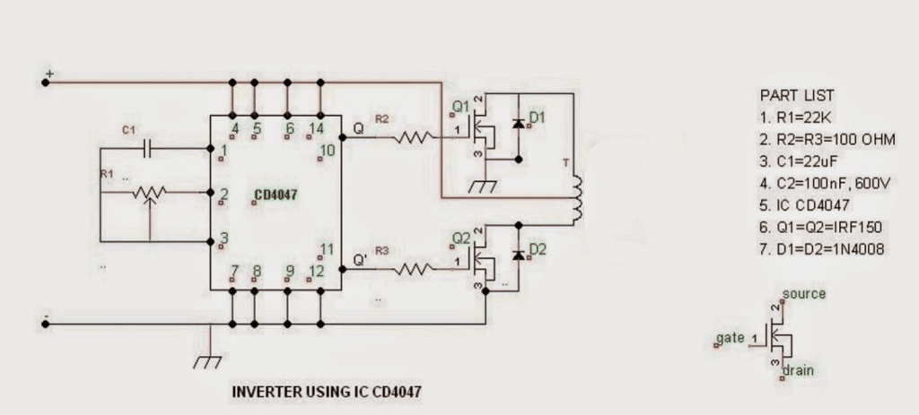
How to Make the Flip Flop Circuit
The flip flop or the alternate switching of the stator coils can be implemented simply by using the circuit shown below.
The circuit is not complicated at all, the entire configuration is built around the IC 4047 and the switching is done with the help of two mosfets.
The center tap of the coil can be seen terminated to the positive while the ends of the coils wires are connected with the mosfet drain.
The RPM can be controlled with the aid of the shown pot.
Flip Flop Schematic
Precautions Before Building the Flynn Motor
A few things that must be taken into account while building the above explained Flynn motor.
The dimensions of the test prototype must not exceed that of a normal fan motor.
The magnets should not be too strong, a rule of thumb is to select a cross sectional area that may be 50% less than the enclosing surface of the stator.
The RPM must not be made too rapid, the Flynn motor is said to work the best at lower RPMs where it is able to generate exceptional amounts of torque compared to the fed electrical input.
The gap between the rotor and stator surfaces must not exceed the 0.5mm mark.
https://www.homemade-circuits.com/making-flynn-motor-circuit-diagram/
Δεν υπάρχουν σχόλια:
Δημοσίευση σχολίου
Το blog TEO O ΜΑΣΤΟΡΑΣ ουδεμία ευθύνη εκ του νόμου φέρει σχετικά σε άρθρα που αναδημοσιεύονται από διάφορα ιστολόγια. Δημοσιεύονται όλα για την δική σας ενημέρωση.