Some breadboard power supplies have adjustable voltage linear regulators to control the required output voltages. Efficiency of the linear regulators decrease as output power increases.
Presented here is a circuit that uses a switch-mode regulator to regulate output voltage. This circuit can be used as power supply for breadboard and testing prototypes.
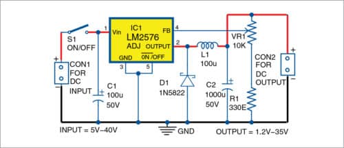
The circuit, as shown in Fig. 1, is built around switch-mode buck regulator LM2576 (IC1), inductor (L1) and a few other components. LM2576 series regulators offer high efficiency and are popularly used to replace three-terminal 78xx series linear regulators.

Fig. 1: Circuit diagram of the breadboard power supply
LM2576 regulators are monolithic integrated circuits (ICs) that provide all active functions for step-down (buck) switching regulators, and are capable of driving 3A load with excellent line and load regulation. These substantially reduce size of the heat-sink, and in some cases eliminate the need for a heat-sink.
LM2576 regulators require least number of external components, are simple to use, and include fault protection and fixed-frequency oscillator. The adjustable version of LM2576 has been used in this circuit.

Input supply is given to connector CON1. Input capacitor C1 attenuates the ripples in the input power supply. IC1, L1 and diode D1 perform step-down operation that converts high input voltage into low output voltage.
Capacitor C2 acts as the buffer. D1 is used as a freewheeling diode to circulate current when switch S1 is turned off. Feedback is provided by voltage divider network, which consists of a fixed resistor (R1) and a variable resistor (VR1 potmeter). VR1 is used to vary output voltage, which can be calculated using the following relationship:
Vout=1.23 [1+(VR1/R1)]
Construction and testing
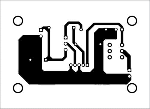
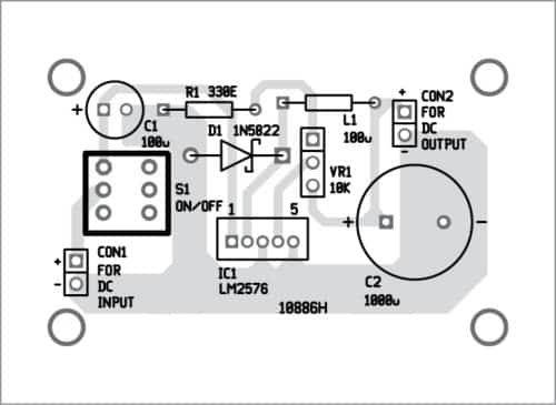
A PCB layout of the circuit is shown in Fig. 2 and its components layout in Fig. 3. Enclose the PCB in a suitable plastic box. Use 2-pin connectors for CON1 and CON2.

Fig. 2: PCB layout of the breadboard power supply

Fig. 3: Components layout for the PCB
Download PCB and Component Layout PDFs: click here
Note. Maximum input voltage of IC is 40V (60V for HV version). L1 must have minimum current rating of 1A. To maintain stability, C1 leads must be kept short and it should be placed near the regulator. IC1 can be fitted with a heat-sink, if required.
A. Samiuddhin, a circuit designer, is B.Tech in electrical and electronics engineering. His interests include LED lighting, power electronics, microcontrollers and Arduino programming.
https://www.electronicsforu.com/electronics-projects/hardware-diy/breadboard-smps-circuit

Δεν υπάρχουν σχόλια:
Δημοσίευση σχολίου
Το blog TEO O ΜΑΣΤΟΡΑΣ ουδεμία ευθύνη εκ του νόμου φέρει σχετικά σε άρθρα που αναδημοσιεύονται από διάφορα ιστολόγια. Δημοσιεύονται όλα για την δική σας ενημέρωση.